Table of Contents
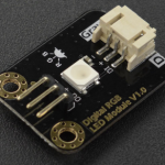
This is a standard DFRobot digital RGB single LED module (DFR0605). It is made up of Red, Blue, and Green LED’s which are individually varied in intensity by the Kookaberry.
The different intensities combine to provide different hues of colour. Each constituent coloured LED has 256 possible levels of intensity (called luminance). The three LEDs lit in combination give an appearance of a coloured hue. The total range of possible hues (called the colour gamut) then is 256 to the power of 3, which is 16,777,216 different hues!
For further information go to “The Ultimate Guide to Understanding Hue, Tint, Tone and Shade” by Shirley Williams, founder of ColourWheelArtist
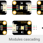
Single RGB LED modules can be strung together (concatenated) to form a long chain of individually addressable LED’s that can all be different colours at the same time.
Alternatively, they can be bought in ready-made strips of RGB LED’s or ready-assembled into panels to form a display screen

Specification
-
LED Type: WS2812 RGB 5050 LED
-
Input Voltage: 3.3V~5.5V
-
Maximum Current: 48mA
-
Quiescent Current: 0.7mA
-
Interface: Gravity 3P Digital
-
Dimension: 30.0mm*22.0mm / 1.18*0.87 in
Linking RGB modules together
Modules can be linked together with three wires in a long daisy chain.

[Explanation with thanks to The Hook Up]
How does it work?
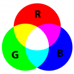
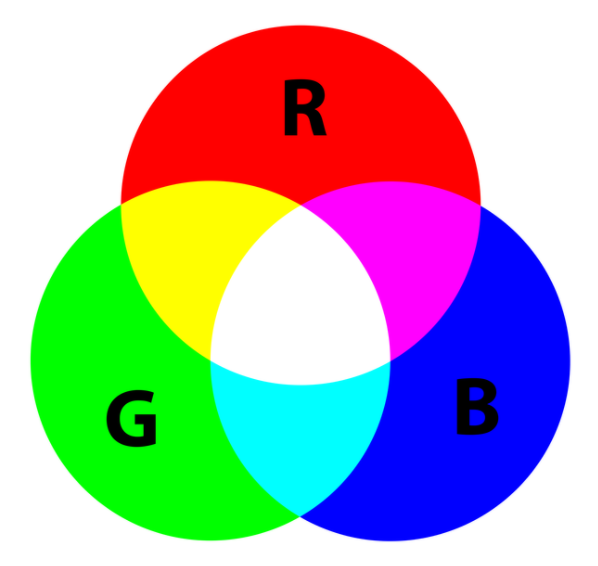
Colour addition
Cramming three Red, Blue, and Green LED’s together in a small package and varying the intensity of each one of them not only varies the colour by addition, but fools the eye – provided it is a little distance away – into seeing what appears to be a single point of colour.

For further information go to this “Colour Addition Tutorial” by the Physics Classroom
Varying Intensity
Sending intensity data each RGB LED in a chain
The intensity (i.e. the level of brightness) of each of the Red, Green, and Blue LED’s making up an RGB module determines its colour. But how does each LED know what level to shine at; and how can they be controlled over only three wires?
Each RGB module contains a tiny microcontroller chip that receives data from the Kookaberry over a signal wire. The other two wires (3.3v and Ground) provide the power to light the diodes and run the LED’s microcontroller.
Each LED microcontroller receives three bytes (8 bits to each byte) of data on the signal wire, each byte being associated with one of the three LEDs. The data in the byte is a number with range 0 to 255 inclusive which is interpreted as the desired intensity of the associated LED.
As the RGB LED modules are in cascade, the three bytes of data are sent downstream by each RGB LED module when new data is received by the module attached directly to the Kookaberry (just like the pass the parcel game).
When the Kookaberry finishes sending data bytes it sets its data line to 1 for a longer period (like when the game music stops) which is interpreted by the RGB LEDs as a signal to update the LED intensities with the three bytes of data currently received.
To the Kookaberry, a chain of RGB LEDs is treated as a long array of 3 byte integers [(RGB0),(RGB1),(RGB2),(RGB3), etc ,(RGBn)].
When only one RGB LED is used, the process is exactly the same but with only the RGBO bytes populated.
Varying the intensity of each LED in a RGB LED
So now each RGB LED module has the intensity data for its three LEDs. The microcontroller in the module now can set the LED intensities using pulse width modulation.
A digital signal can only be either ON (“1”) or OFF (“0”). So if a LED is controlled by a simple digital signal it can only be fully ON (maximum intensity) or fully OFF (zero intensity).
However, if the digital signal is switched (pulsed) rapidly ON and OFF – with the width of the OFF time greater than the width of the ON time – the average power to an individual LED will be less than maximum, and the intensity will be proportional to the width of the ON time.
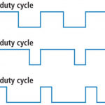
The percentage of time that a digital signal is ON over an interval or period of time is called the Duty Cycle. This period is the inverse of the frequency of the waveform.
If a digital signal spends half of the time on and the other half off, we would say the digital signal has a duty cycle of 50% and resembles an ideal square wave. In this case the intensity of the LED would be half its maximum value.
If the percentage is higher than 50%, the digital signal spends more time in the ON state than the OFF state and vice versa if the duty cycle is less than 50%. Here is a graph that illustrates these three scenarios:

If the frequency is fast enough (typically >50Hz) the eye’s persistence of vision will make the LED appear to be on all the time without any flickering
This process is called Pulse Width Modulation (PWM)
Where can I find them in the real world?
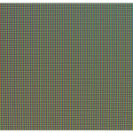
RGB LED’s are the individual pixel elements in colour screens on your devices and on TV’s. Individually addressable RGB LED’s are linked together in columns and rows and number in the millions in standard 4k LED TV’s.
8,294,400 to be precise, because, in a 4K TV, there are 4,096 pixels across the horizontal dimension and 2,160 in the vertical.

For further information go to “What pixels are and what they mean for TV viewing” by Robert Silva for Lifewire