Table of Contents
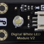
This LED is supplied by DFRobot (DFR0021-W). Unlike normal LED’s connected in a breadboard circuit, it has three wires rather than two. The reason for this can be found later on in this description.
Specification
-
Type: Digital
-
PH2.0 socket
-
White LED light module
-
Lights when Signal pin is set to High (“1”)
Blinking an LED
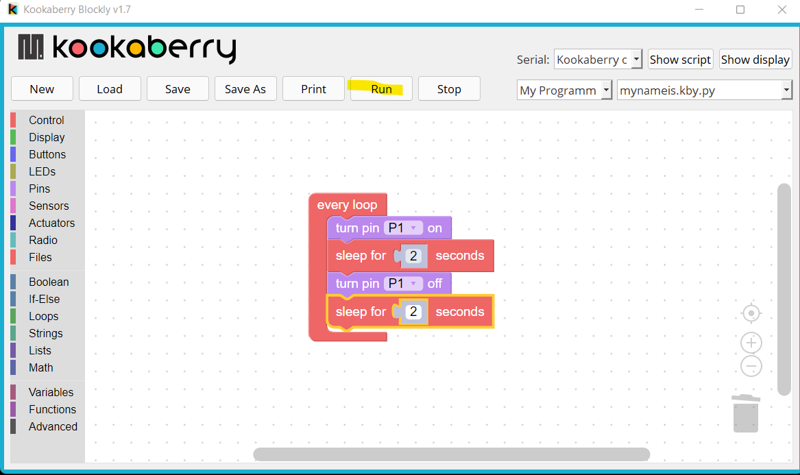
Connect a Kookaberry to your PC or Mac, and plug the LED Module into socket P1 on your Kookaberry. Go to the KookaBlockly Support page for help in setting up.
Open KookaBlockly and create the programme shown below to blink the LED.
Go to the KookaBlockly tutorial Blink an LED and send a distress signal for more fun with LED’s
LED composition
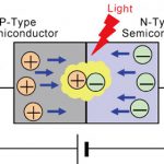
A LED is made up of two different semiconductor materials placed close together to form a diode. When a voltage is applied, a current flows across the barrier between the two materials. This current causes negatively charged free electrons from the n-type semiconductor to move across the barrier into the p-type material and the holes in the p-type material to travel in the opposite direction.

An electron has a higher energy level than a hole, so when they collide and merge, the electron gives up energy in the form of a photon – which is a unit of light.
The energy released in a photon depends on the material and processing of the semiconductor materials. This energy determines the frequency, and therefore the colour, of an LED.
Why does the DFRobot LED have three wires?
Normal LED’s, being digital devices, need only two wires (Volts and Ground), and are always either fully ON or fully OFF.
However, the LED supplied by DFRobot in our kits has three wires and an inbuilt circuit. This circuit permits constant power to be supplied to the LED components from the Kookaberry over two of the wires whilst receiving data over the third (Signal) wire to vary the intensity of the LED.
In normal operation when the provided LED is connected to the Kookaberry and is instructed by the algorithm in an app to turn ON; the Kookaberry lifts the voltage on the Signal wire from 0 to 3.3 volts. The LED then shines at maximum intensity until the voltage on the signal wire is returned to zero.
[Note: It is important to recognise the voltage on the Signal wire can only ever be in one of two digital states – OFF or ON.]
However, if dimming is required, then data is sent along the Signal wire to vary the intensity.
Dimming an LED
Microprocessors work at a fixed DC voltage (Vcc) depending upon the design of their integrated circuits. The Kookaberry’s IC’s use a Vcc supply voltage of 3.3 volts. Vcc is also the voltage used to provide power over two wires (Vcc and Ground) to peripherals and cannot be varied.
The current drawn by a peripheral is also a constant determined by its resistance (V=IxR).
Dimming a LED, or controlling the speed of a DC motor like the DC Fan supplied in the Class Kit, requires that the power (Volts x Amps) being provided from the Kookaberry is reduced.
How is it possible to reduce power when neither the voltage (Vcc) or the current can be varied?
Pulse Width Modulation
If the digital signal is switched (pulsed) rapidly ON and OFF – with the width of the OFF time greater than the width of the ON time – the average power to an individual LED will be less than maximum, and the intensity will be proportional to the width of the ON time.
The percentage of time that a digital signal is ON over an interval or period of time is called the Duty Cycle. This period is the inverse of the frequency of the waveform.
If a digital signal spends half of the time on and the other half off, we would say the digital signal has a duty cycle of 50% and resembles an ideal square wave. In this case the intensity of the LED would be half its maximum value.
If the percentage is higher than 50%, the digital signal spends more time in the ON state than the OFF state and vice versa if the duty cycle is less than 50%. Here is a graph that illustrates these three scenarios.

If the frequency is fast enough (typically >50Hz) the eye’s persistence of vision will make the LED appear to be on all the time without any flickering
This process is called Pulse Width Modulation (PWM)