Table of Contents
This Tutorial describes PWM and how it’s principles can be demonstrated using the Kookaberry ecosystem.
Overview
Specifically, this Tutorial will describe how the speed of a motor or the intensity of an LED is controlled in the digital world.
The analogue world
Our real world is generally an analogue world. Our eyes perceive a continuous range of brightness and colour, and our ears a continuous spectrum and level of sound.

In a totally analogue world (not so very long ago) the speed of a motor, or the volume of a radio, or the dimming of a light, was controlled by continuously varying the power of the source providing the energy. This was often achieved by varying the applied voltage using a potentiometer such as is provided in the Journey Class Kit.
The digital world
The digital world, on the other hand, doesn’t naturally do continuous….. It only knows two states ON or OFF; High or Low; 1 or 0.
This can be demonstrated by running the Analogue app on the Kookaberry with a potentiometer as an input and a motor or a LED as the output. When the input voltage reaches a threshold level, it triggers an output signal that turns on the LED or a motor.

The potentiometer is an analogue input device which adjusts the voltage at the input connector (P4) between Vcc (3.3v) and Ground (0v). The Kookaberry can recognise analogue signals on P4 and converts it to a digital signal by sampling and measuring the instantaneous level at high speed. The circuit that does this is called an Analogue-to-Digital Converter (ADC).
Micropower considerations
Microcontrollers work at a fixed DC voltage (Vcc) depending upon the design of their integrated circuits. The IC’s in the Kookaberry use a Vcc supply voltage of 3.3 volts. Vcc is also the voltage used to provide power over two wires (Vcc and Ground) to peripherals and cannot be varied.
The current drawn by a peripheral connected to a microcontroller is also a constant determined by Ohm’s Law (Volts=CurrentxResistance).
Dimming a LED, or controlling the speed of a DC motor like the DC Fan supplied in the Class Kit, requires that the power (Volts x Amps) being provided from the Kookaberry is reduced.
How is it possible to reduce power to a peripheral when neither the voltage (Vcc) or the current can be varied?
Simulating “Continuous” in the digital world
Pulse Width Modulation
If the power feeding a peripheral such as a LED or motor is switched (pulsed) rapidly ON and OFF by a digital signal – with the width of the OFF time greater than the width of the ON time – the average power to the peripheral will be less than maximum, and the power will be proportional to the width of the ON time.
This process is called Pulse Width Modulation or, more generally, PWM.
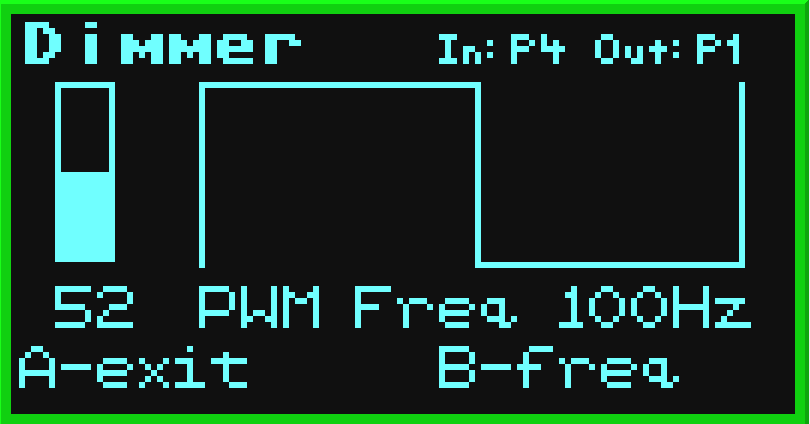
It can be demonstrated by running the Dimmer app on the Kookaberry with a potentiometer as an analogue input and a LED as a digital output. If the DC Fan (a motor) is used instead of the LED, then the same PWM process will vary its speed


PWM Duty Cycle
The percentage of time that a digital signal is ON over an interval or period of time is called the Duty Cycle. This period is the inverse of the frequency of the waveform.
If a digital signal spends half of the time on and the other half off, we would say the digital signal has a duty cycle of 50% and resembles an ideal square wave. In this case the intensity of the LED would be half its maximum value.
If the percentage is higher than 50%, the digital signal spends more time in the ON state than the OFF state and vice versa if the duty cycle is less than 50%. Here is a graph that illustrates these three scenarios. They are also the scenarios used in the screenshots above.

Persistence of vision
When PWM is used to dim lights, the frequency of the waveform should be greater than 50Hz so that the eye’s persistence of vision makes it seem that is ON all the time and does not flicker.
This can be demonstrated in the Dimmer app by reducing the frequency of the PWM waveform by pressing Button B. The frequency can be varied in steps from 16Hz to 100Hz.

Where is PWM used?
In our increasingly digital world PWM is becoming the predominant process for varying illumination level; speed; and direction and positional control.
Illumination
The intensity of LED lighting and the LED’s in your TV is controlled by PWM. See the explanation of the process for the RGB LED.
Speed
The small DC motors used in model cars and tracked vehicles (such as a Mars Rover), and in robotics, all use PWM to control their speed.
Direction and positional control
A form of PWM is used to control the angle that a servo moves through. An example might be when a servo is used to control the steering wheel of a model car or the position of a robotic arm.
In this case, the duty cycle is not important, as the width of the pulse determines how far the armature of the servo moves. See this explanation from Sparkfun